
Documentation
Documentation
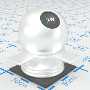
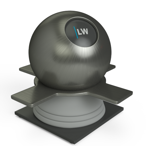
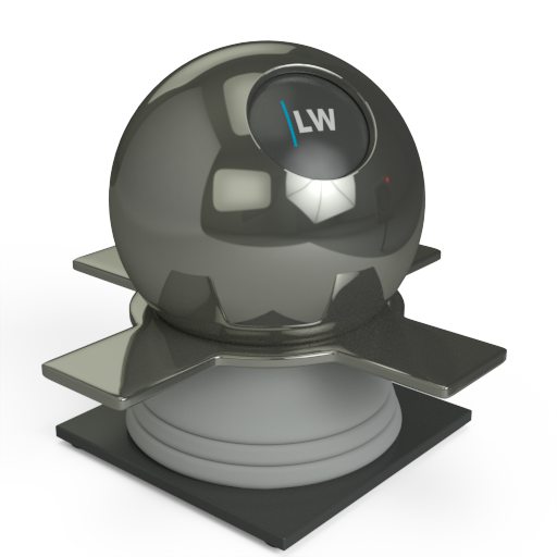
A component for representing the specific reflectance properties of metals. In the real world, reflections and specular highlights in metals are affected by the color of the metal itself. This behavior differs to plastics, where reflections exhibit the same color as that of the incident light.
Although metals are typically quite reflective, the actual amount of reflectance varies somewhat depending on the angle of view, so that very shallow angles give higher levels of reflectance. (This effect is not as pronounced as when seen in shiny plastics or water.) A metal's reflectance is specified by setting the Index of Refraction (IOR). In this case IOR refers to the absorption of the material rather than, for example, the refraction of light rays through glass. A relatively high IOR (for example: 15 - 30) will result in a falloff curve typical of metal.
This is the same as the Conductor component with additional control over Anisotropy.
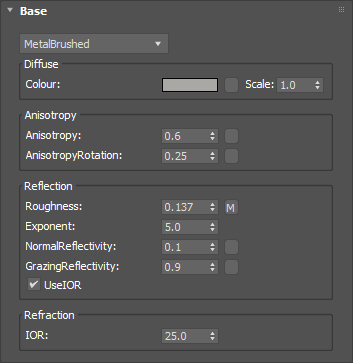
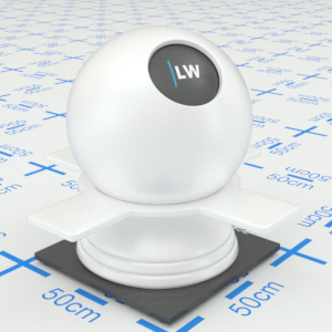
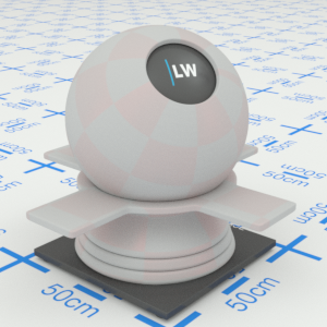
The basic color of the component. This can be a single color value or a texture map.
Input: Color or Map

Click material thumbnail for larger view
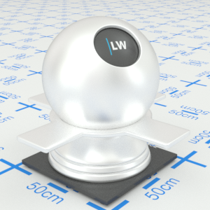
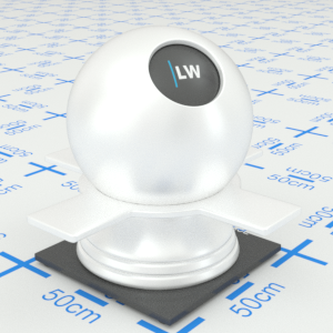
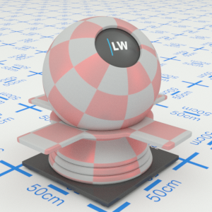
Simulates the effect of reflections on brushed or machined surfaces where there are parallel scratches or grooves. Reflections tend to get stretched out in a direction orthogonal to the scratch direction. Higher values will increase stretching. Anisotropy works in conjunction with the Roughness parameter.
Input: 0.0 – 1.0 or Map


Click material thumbnail for larger view
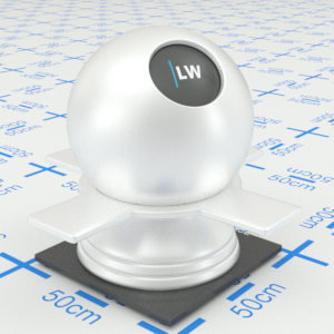
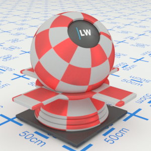
Controls the direction in which the reflection is stretched, relative to the texture coordinate axis at that point. The range is 0.0 to 1.0, where 1.0 means 360˚, 0.25 means 90˚, etc. To work this out, simply multiply the value by 360. You can also apply a texture map, for example to get a circular brushed effect.
Input: 0.0 – 1.0 or Map

Click material thumbnail for larger view
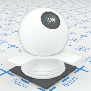
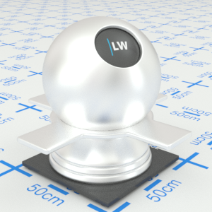
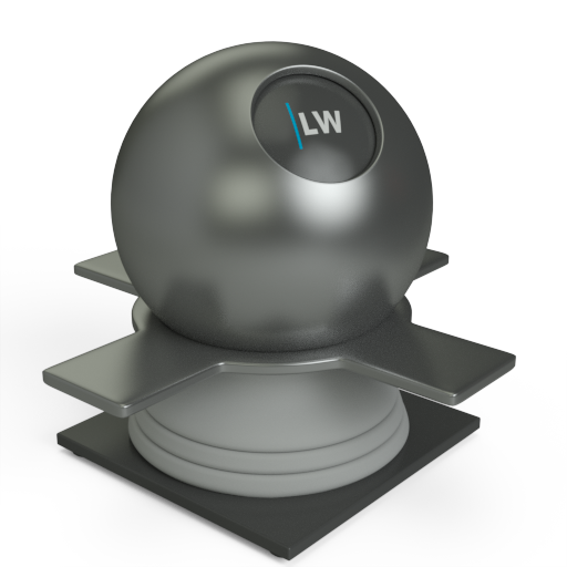
Simulates the level of polish. Higher values will result in more blurred reflections.
Input: 0.0 – 1.0 or Map


Click material thumbnail for larger view
Controls how quickly the shininess changes between the normal and grazing values as you move across the surface.
Range: 0.01 – 25.0

Click material thumbnail for larger view
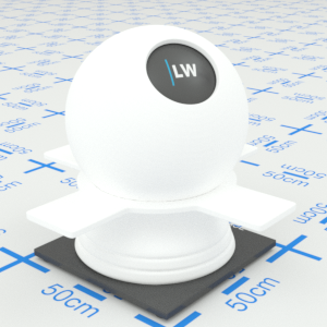
Controls how shiny the object appears when viewed straight on. Materials of this type typically display little reflectance at 0˚ to the camera.
Input: 0.0 – 1.0 or Map

Click material thumbnail for larger view
Controls how shiny the object appears when viewed at a very shallow angle. Materials of this type typically display higher reflectance at 90˚ to the camera.
Input: 0.0 – 1.0 or Map


Click material thumbnail for larger view
Ignores all other parameters in the Reflection group and uses the IOR parameter (see below) to define the falloff curve.
Input: On/Off Checkbox
Index of Refraction. Controls the amount of reflection and shape of the falloff curve. UseIOR must be ticked.
Range: 0.0 – 50.0


Click material thumbnail for larger view
Gives control over the contribution of the layer to the overall material appearance. A value of 1.0 will completely block any effect of any material layers below. A value of 0.0 will remove the layer's contribution to the overall material appearance.
Input: 0.0 – 1.0 or Map
Click material thumbnail for larger view
Allows you to set a bump map to simulate surface detail and to control the intensity and orientation of the effect.
Input: 0.0 –, or Map


Click material thumbnail for larger view
Click material thumbnail for larger view
Base
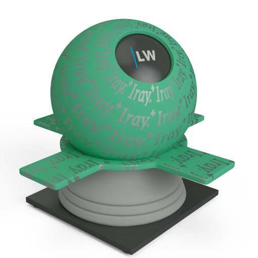
Decal
Last edited: