
Documentation
Documentation
A component for representing the specific reflectance properties of non-metals such as plastics. The reflections are not affected by the material's color but are defined by the incident light.
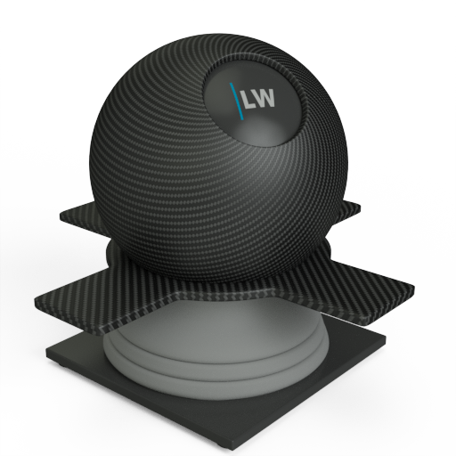
This component follows Fresnel's Law where the amount of reflectance varies based on the angle of view. For example, viewing a carbon fiber type object at very shallow angles results in almost complete reflectance whereas looking straight on, the object exhibits less reflectance. This Fresnel falloff can be defined explicitly by setting reflectance values for 0˚ (when looking at the middle of a spherical object) and 90˚ (when looking at a spherical object's edge). You can define how quickly the falloff varies between 0˚ and 90˚ via an exponent parameter. The Fresnel effect can also be controlled by specifying the Index of Refraction, which effectively defines the above values for you.
This is the same as the Dielectric component with additional control over Anisotropy.
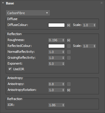
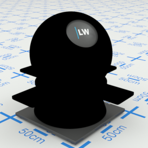
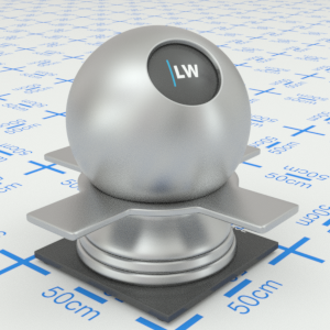
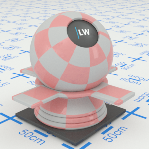
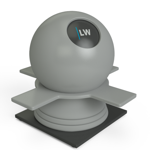
Defines the basic color of the component. This can be a single color value or a texture map.
Input: Color or Map
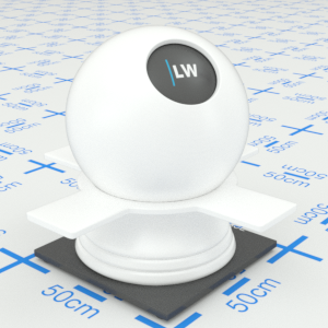

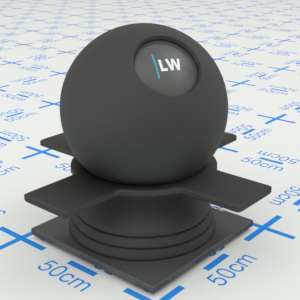
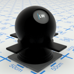
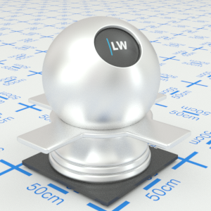
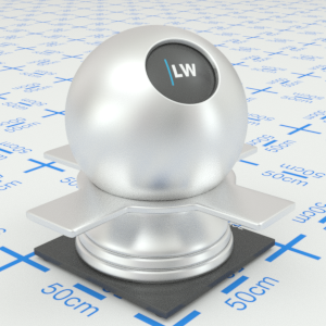
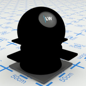
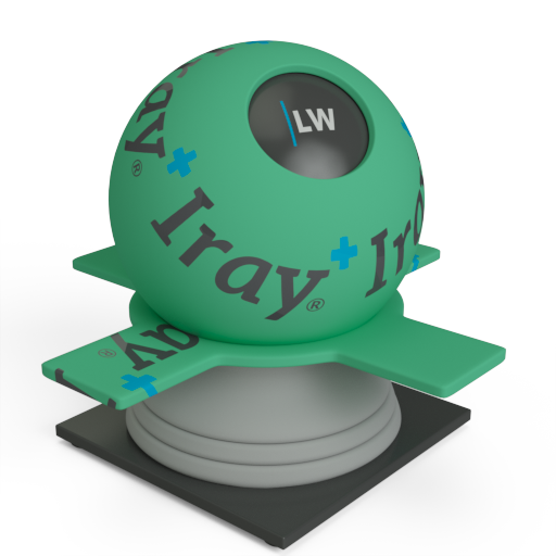
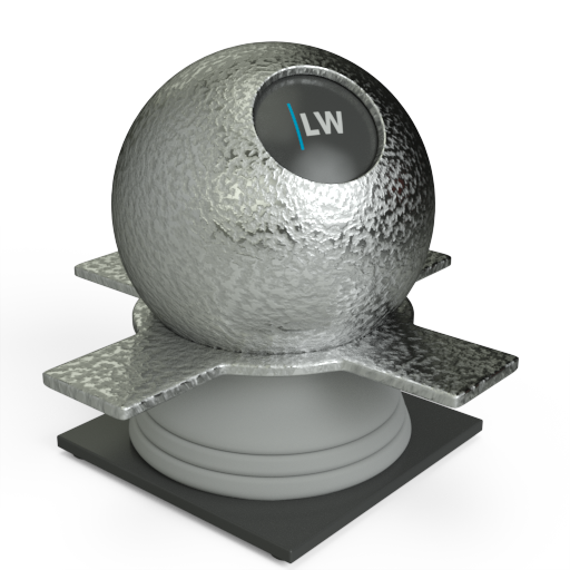
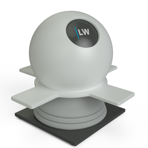
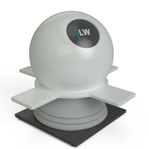
Click material thumbnail for larger view
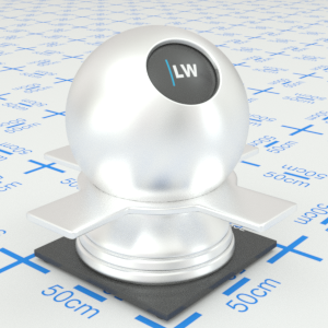
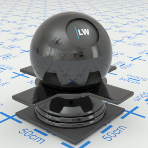
Simulates the level of polish. Higher values will result in more blurred reflections. Can be used to create powdery or frosted looking materials.
Range: 0.0 – 1.0 or Map

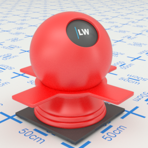
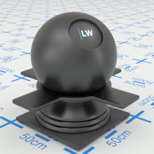
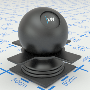
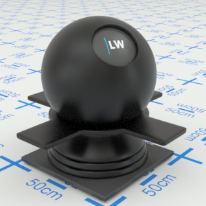
Click material thumbnail for larger view
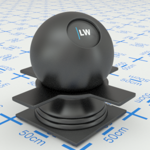
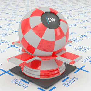
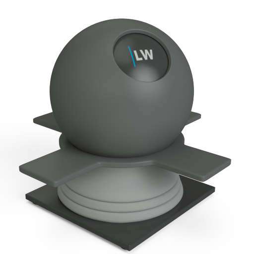
Can be used to control the color of reflections or, using grayscale, the amount of reflections.
Input: Color or Map

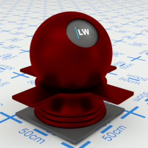
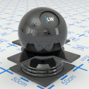
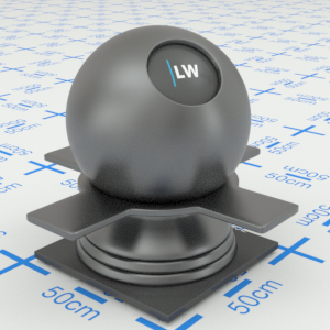
Click material thumbnail for larger view
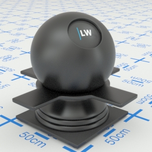
Controls how shiny the object appears when viewed straight on. Materials of this type typically display little reflectance at 0˚ to the camera.
Input: 0.0 – 1.0 or Map
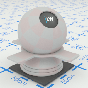
Click material thumbnail for larger view
Controls how shiny the object appears when viewed at a very shallow angle. Materials of this type typically display higher reflectance at 90˚ to the camera.
Input: 0.0 – 1.0 or Map

Click material thumbnail for larger view
Controls how quickly the shininess changes between the NormalReflectivity and GrazingReflectivity values as you move across the surface.
Range: 0.01 – 25.0

Click material thumbnail for larger view
Ignores the NormalReflectivity, GrazingReflectivity, and Exponent, settings, and instead uses the IOR parameter (see below) to define the falloff curve.
Input: On/Off Checkbox
Simulates the effect of reflections on brushed or machined surfaces where there are parallel scratches or grooves. Reflections tend to get stretched out in a direction orthogonal to the scratch direction. Higher values will increase stretching. Anisotropy works in conjunction with the Roughness parameter.
Input: 0.0 – 1.0 or Map


Click material thumbnail for larger view
Controls the direction in which the reflection is stretched, relative to the texture coordinate axis at that point. The range is 0.0 to 1.0, where 1.0 means 360˚, 0.25 means 90˚, etc. To work this out, simply multiply the value by 360. You can also apply a texture map, for example to get a circular brushed effect.
Input: 0.0 – 1.0 or Map


Click material thumbnail for larger view
Index of Refraction. Controls the amount of reflection and shape of the falloff curve. UseIOR must be ticked.
Range: 0.0 – 50.0
Click material thumbnail for larger view
Gives control over the contribution of the layer to the overall material appearance. A value of 1.0 will completely block any effect of any material layers below. A value of 0.0 will remove the layer's contribution to the overall material appearance.
Input: 0.0 – 1.0 or Map
Click material thumbnail for larger view
Allows you to set a bump map to simulate surface detail and control the intensity and orientation of the effect.
Input: 0.0 –, or Map


Click material thumbnail for larger view
Click material thumbnail for larger view
Base
Decal
Coating


Last edited: